|
|
| Upcoming Features... personalized main page, discussion forum, workbench calculator... |
|
Build a ‘T-40’ Solid State Analyzer by Terence Thomas If you have ever put together an electronic circuit with meticulous care, only to find out that it doesn’t work, then you know the frustration of being an electronics experimenter. Unfortunately this marks the end of some budding careers and it presents quite an annoying problem to the professional engineer.
The primary source of problems experienced in the first stages of prototype
construction is inconsistencies in the performance parameters of semiconductors.
Nearly fifty percent of solid state devices exhibit some significant deviation
from the norm. In a perfect world, parts would perform with uniformity but in
the real world this is not the case. To make sure you are working with
semiconductors that are functioning properly, you need a device that gives you a
variety of tests which can assure that the best component is chosen for a given
circuit. The T-40 solid state analyzer is just that device. 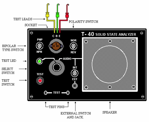 GO NO-GO
All testers on the market perform a simple go no-go test, which merely confirms
that a transistor will function under most conditions. The T-40 Analyzer also
has this capability. A PNP-NPN toggle switch enables you to test both types of
bipolar transistors. To test, put a transistor in the socket and select the
type. If you do not know the type, try both positions. When you press the test
button the LED should glow brightly, green for PNP and red for NPN. If the LED
is dimly lit before you press the test button, the transistor is leaking and
therefore has a narrow dynamic range and is limited to certain applications. A
fully lit LED, without pressing the test button, indicates a device that is
shorted out and if the LED does not light when the test button is pressed, the
device is open and is not usable for any purpose. 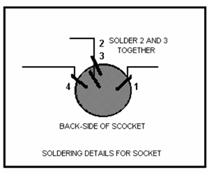 The normal-reverse toggle switch reverses the emitter-collector leads and allows you to identify the proper lead arrangement on unmarked transistors. Three test leads enable the user to test devices in circuit or power transistors that will not fit in the test socket. FETs, SCRs
FET transistors are tested in the same way as bipolar with the gate lead
equivalent to the base lead of a bipolar. The drain and source leads are
interchangeable. SCR devices also have a gate lead but the anode and cathode
leads are equivalent to the collector and emitter of the bipolar transistor
respectively. When testing an SCR, the LED should come on when the test button
is pressed and stays on after the test button is released. 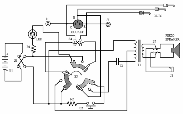 AUDIO TEST A feedback oscillator is included in the analyzer, which uses the transistor under test as the drive element. Three parameters will provide information that will enable you to select the best transistor for the job. Pitch is the first determining factor. A rotary switch is provided to switch from go no-go mode to audio mode. With the rotary switch in the audio position and a transistor in the socket, you should hear a pitch. If it is very high, try switching the NOR/REV switch. The lower pitch will give you the proper emitter/collector orientation. Volume is also an important factor and should be louder in the correct position. The third parameter is tonal quality. A raspy tone is less likely to be the proper lead orientation than a pure tone. Transistors with a strong clear signal will work better in circuits requiring a wide dynamic range. After a time, you should become quite an expert at matching transistors in this
manner. It is amazing how much useful information an astute experimenter,
willing to devote some time to this mode of operation, can gather. 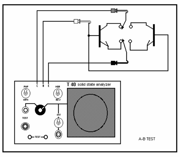 An A-B test circuit is shown in an illustration that can enable the user to make quick comparisons between two transistors. It can be set up on a circuit designer or you might want to put together a permanent two-socket outboard test unit for matching transistor characteristics. OSCILLOSCOPE MONITORING
Two test posts are provided at the bottom of the unit that can be used to
monitor the audio signal on an oscilloscope. This will facilitate an in depth
analysis of any device under test. Wave shape analysis by this method can be a
valuable source of information in the fabrication of prototypes. 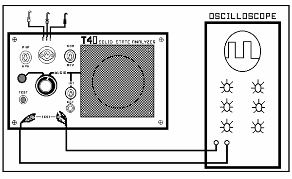 CONTINUITY TESTING In the go no-go mode the test posts can be used as a continuity tester for wires and cables. Diodes can be tested using the posts and with the addition of two test leads, circuit continuity tests on circuits can be performed. A-B TEST When performing the A-B test, first make sure that both transistors have been checked out for proper collector-emitter polarity. Then place the two transistors in the test circuit and switch from A to B. If the pitch or volume of the two is considerably different, chose the transistor that exhibits the stronger clearest tone and then compare other transistors to it. CONSTRUCTION
A 6 ¼, by 3 ¾, by 2-inch plastic project box was chosen but the metal cover
plate proved to be too flimsy, so a circuit board was cut to size to provide
more stability. All switches, socket, micro-mini jack, speaker, test leads and
binding posts are mounted to the front panel. As we can see on the backside of
the faceplate, there are also two circuit boards. One is mounted over the socket
that is connected to the test leads to provide a stable connection point. The
socket shows 4 holes but the upper and center socket connections are soldered
together to accommodate both in line transistors or triangular lead arrangement.
Circuit board two serves as a mounting platform for the audio transformer and
capacitor. 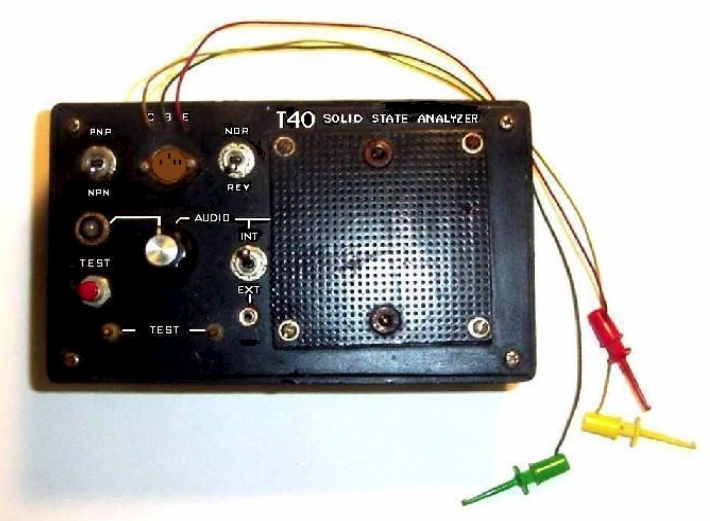 Wiring is point to point with a five terminal strip added to accommodate points that are not anchored elsewhere. The two miniature binding posts are actually mounted backwards (Solder side out), and should be isolated from the foil on the back of the faceplate with a piece of tape. Since the analyzer will most likely become the most popular test instrument on your bench, it is important to make the unit mechanically stable. A 2 ¾ inch square piece of perforated matrix board and a piece of matte board with a hole cut to match the speaker are used to mount the flat Piezo speaker from the front. A Piezo speaker was chosen because its impedance is 1K ohms, making it ideally suited to the circuit requirements of breadboard experimental circuits. Another piece of perf-board is used, like a sandwich, to hold the speaker in place. Just above this board is the 9 volt battery in a holder that is glued to a perf-board. The second board is mounted over the test socket to relieve joint stress due to test lead movement. MAIN BOARD LAYOUT 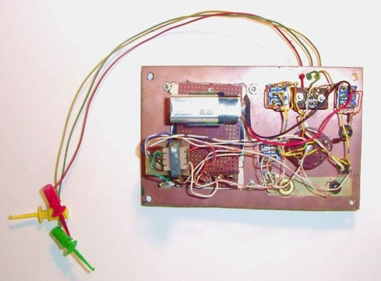
As you can see in the illustration, the layout is quite straightforward. The
transistor polarity switch is in the upper left corner. Next are the test socket
and extension leads. Collector/ emitter reversing switch is on the right side of
the socket. Below that is the internal/external switch and micro-mini jack that
provides access to the piezo speaker. In the center of the controls is the
rotary switch that determines the mode of operation. A dual direction LED is
mounted to the left of the rotary switch and functions as an indicator for the
go no-go test. Just below that are the test switch and test posts. The piezo
speaker is to the right of the controls. 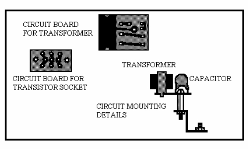 CIRCUIT LAYOUT
In the circuit photo you can see component layout. Starting
at the lower left, we see the audio transformer and capacitor mounted on one of
the circuit boards. The battery just above is secured with a battery clip glued
to the rear support board for the speaker. All toggle and push button switches,
socket assembly, test leads, mini jack, LED and rotary switch are mounted in a
cluster on the right hand side (From the rear), of the circuit board. Since all
parts are mounted on the face plate removal of the circuit for battery
replacement is easy. 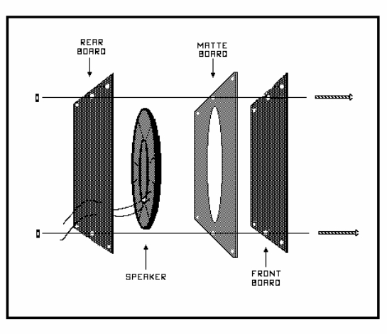 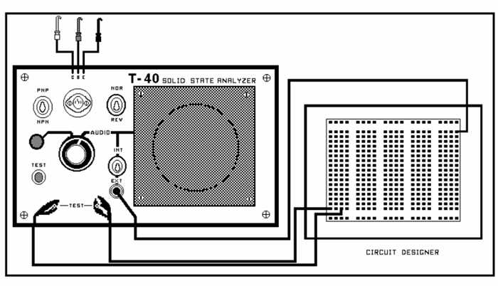 CONCLUSION Although the T-40 is a fairly simple, it is remarkably versatile and can provide you with a test facility that has no equal when it comes to the analysis of solid state performance.
PARTS LIST
LED
Socket
Clips
Terminal strip
Capacitor
Jacks
Transformer
Batteries Circuit boards
Terence Thomas
|
|
WorkbenchFun.com is a trademark of electricalfun.com © 2009 Project Submission Guidelines |