Is chaos having an effect on your circuit building?
It is said that there is nothing new in the universe and nothing is
further from the truth. Every nanosecond is unique and nothing is ever
repeated. No matter how many times you do anything, that seems repetitive,
it is not. Every physical element has changed from one moment to the next
and for the most part, these minute changes have little effect on the
outcome of most procedures. So many of the changes are so infinitesimal that
they are not even perceived.
Every now and then, circumstances beyond your perceptions seem to
conspire to frustrate your efforts to do meaningful work. Our universe was
born out of chaos called the big bang, and chaos is everywhere.
Each and every grain of sand is uniquely shaped, as is each and every
speck of dust or particle in the air. There are no exact duplicates of
anything and each and every particle has characteristics unique to it. This
makes substances, to one degree or another, inconsistent.
Subatomic Consistency
Subatomic particles cannot be seen and will always remain just theory. If
the character of mater in basic physics is patterned in a given fashion,
then it is reasonable to assume that the same or similar exists on the
quantum level, or does it? That is a question, which will not be answered
anytime soon.
Chaotics
"Chaotics is the study of the predictability of complex systems." as Jeff
Goldblum explains to Laura Dern in the movie "Jurassic Park". Because of the
inconsistency of matter, there is more often no predictability. The number
of significant variables in substances and conditions make manufacturing of
anything accurate only within a plus to minus factor.
Randomness is the rule of the universe and this complicates any
organizational process. Anything that contributes to the deterioration,
decomposition, or alteration of any substance may be considered an element
of chaos. Corrosion, oxidation, decay, atmospheric temperature differential
and tensile stress, as well as elements we are not aware of can produced
changes in solid material.
Order
Order is an illusion. It is an invention of man for the
purpose of control and to create aesthetically pleasing visual environments.
Symmetry is that which seems equal in all planes and it is also an illusion.
It is difficult to understand how the quantum community could even entertain
the idea of a singularity because of the inconceivable set of circumstances
necessary to create such an unlikely phenomenon. Equal pressure from all
angles is just not a symmetric possibility.
What's it all about
What does all this have to do with electronics? Since electronic
components are made of substances that are imperfect, then imperfect devices
will be the results. For example, substances used in the manufacture of
resistors is rated at plus to minus a percentage. Transistors with the same
component number behave differently in the same circuit. In addition, heat
generated by components can change the value of that and other components.
Dust and other floating debris as well as chemical content of the atmosphere
can complicate the circuit design process. Even unknown factors can have an
effect on the circuit designing process as evidenced by the fact that
sometimes even veteran circuit designers have given up on prototypes with
extremely stubborn problems.
What to do
Because of the infinite number of variables, chaos is all around us and
it has an effect on everything, and that includes your project. Research
laboratories work on component fabrication in clean rooms that are, for all
practical purposes, free of dust. Chairs and floors are made of conductive
material that prevents static charges from building up. Despite this, even
manufacturers make a dud on occasion. It is not necessary for you to go to
these extremes, however, you can take a few steps to assure your success. It
is a good idea that you also choose a clean, cool, well lit workbench.
Organization is helpful in keeping on top of potential problems.
Circuit designer
It is always best to breadboard a project before you try building it.
This allows you to experiment with a variety of components to optimize the
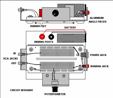
design. Circuit designers, like the one illustrated in this article, can go
a long way to organize your projects. The board itself can be purchased at
your local supplier and when mounted as shown, can make your work more
stable and productive.
The size used in the unit, pictured in this article, measures 2 1/8 by 3
5/8 and contains 23 rows of 5 clips for circuit connection and 2 rows of 20
clips to supply power to the circuit.
As we see in the diagram, a 4-inch by 4-inch piece of Masonic, combined
with 4 rubber feet, serves as a base for the board. A piece of aluminum foil
placed under the board makes an electrical connection between three angle
pieces that act as a hum shield.
Two RCA phono jacks are mounted on one of the angle brackets to connect
to other circuits. A power jack, connected to another angle bracket, enable
the use of an external AC wall unit and a banana jack is also provided. A 9-volt
battery clip is also provided for a freer operation. Don’t forget to disconnect
the battery when using the wall power supply unit.
The circuit board contains rows of clips that provide a solid connection
to any component lead that is inserted into the proper contact hole.
Sometimes the leads do not go into the holes easily so needle nose pliers
can come in handy. The holes spaced to match the pin placement of integrated
circuits. They snap in easily and make stable contact that will assure an
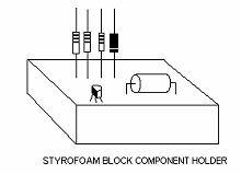
operating circuit. A piece of Styrofoam can be used to store the components
until they are used on the circuit designer.
Connection to other circuits is easily accomplished with the two RCA
phono jacks and adjustment of circuit parameters can be made with the
built-in potentiometer. Shielding provided by the angle brackets should keep
the circuit free of radio and other distortion producing AC signals. Wires
that are used to connect the circuit should also be given a continuity test.
Component preparation
Component leads are without a doubt the most bothersome problem when
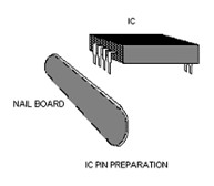
trying to get a circuit working. Integrated circuits are the worst offenders
because of the number of pins. Most ICs have a number of pins that have
enough corrosion to interfere with proper operation and the best way to
handle this is a manicurists nail board rubbed lightly over both sides of
the flat pins until you see them shine.
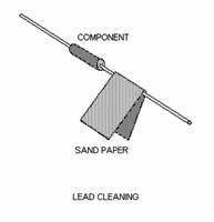
Resistors also tend to have corroded leads and a quick swipe with sandpaper
or scouring pad will assure clean contact. The same goes for capacitors and other components.
Testing
All components should be tested before using in the circuit designer.
Some components, such as LEDs, can be tested on the designer with a small
circuit off to the side. Transistors should be tested with a reliable
transistor tester. Resistors and diodes can be tested with a multimeter.
Resistors
Resistors are made with plus to minus value rating. If there is no fourth
color band on the resistor, there is as much as 20% value variance. If the
4th band is silver, the possible variance is 10% and if the 4th band is
gold, the rating is within 5%. Critical circuits may function better with
more accurate resistors. Precision resistors are also available that are the
most accurate and can run low as 1% but they can be quite expensive.
Capacitors
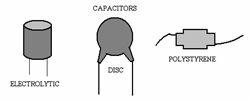
Capacitors that pass the signal from one stage to the next tend to
be less critical when it comes to design parameters, while capacitors
that connect the signal to ground, impart a timing or filter element that
can be quite critical. There are different types of capacitors, disc,
polystyrene, electrolytic, etc. You might try a different type of capacitor
for a given job for it might make a difference.
Integrated circuits can be tested in IC testers, but if you don’t have
one, the circuit you are designing will serve as a tester. If the IC runs
hot, make sure the proper pin connections are made and every thing is properly
in place and if the IC continues to run hot, then the IC is probably bad so try another IC.
If all components have been tested the circuit is wired correctly and it
doesn’t work, then remove everything from the designer board, take a break,
have a drink, and start over in a different place on the designer board. Even
replacing a component with another of the same value may do the trick.
Foil pattern
If you choose to use foil circuit boards there are a few things you should
keep in mind. After you have chosen the board, you should clean it with one of the
commercial steel wool scouring pads and water, until it is shiny. This will assure
that the etching solution will remove all of the excess copper. Make sure that
the etchant bath has removed all of the unwanted copper from the board before removing it.
When you do remove the circuit board, rinse it off with cold water and then
use the scouring pad again to expose the remaining copper. If there are any short
circuits due to excess copper, use a mat knife to scrape of the excess. After the
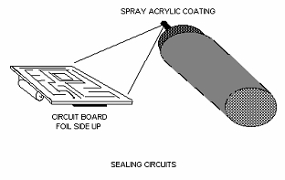
circuit board is completed, you may want to spray the board with an acrylic sealant.
This will prevent any short circuit if the board should come in contact with a wire
or any other conductive element. The spray can be purchased at any art supply store.
Solder
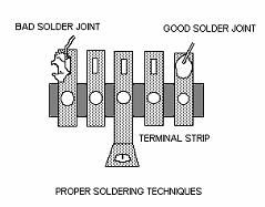
Another problem that can cause circuits to malfunction is poor soldering techniques.
Solder joints should look shiny and smooth, not jagged and dull as shown in the illustration.
You should work on some small projects to develop your skills.
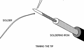
Only use rosin core solder (acid core solder is not for electronic circuits), and
make sure that the soldering iron is hot enough to melt the solder. One way to assure
this is to tin the tip. This is accomplished by melting the solder and let it cover the
very tip of the soldering iron.
Tinning the tip of the iron will make soldering easier. The best technique to soldering
is to heat the work, the foil pattern, or the lug, or tie point, and then touch the solder
to the heated area and let the solder flow over the work. Solder quickly for heat from solder
can burn out components like transistors and ICs, in fact it is best to use sockets when
working with integrated circuits.
If all fails
Circuits for the most part go together quite easily, but every now and then, one gives
you trouble and you just cant figure what is the matter. What you must do is get away from
it for a while, clear your head and then start from scratch. After doing this once, I came
back to the circuit and saw the most obvious mistake you could imagine and every thing
went perfectly after that. "How could I have missed that?" I kept saying too myself.
Conclusion
Chaotic elements may complicate your task in ways you will never be aware of so
you must do what you can to increase your chances for success. This is most important
for the beginner, for failure has greater impact on their confidence. For veteran
experimenters, it can reduce some of the frustration on complex circuit designs. Make
sure that you use these proper procedures, so that the next time a butterfly flaps its
wings, somewhere in the world, your circuit doesn't explode in front of you.
by Terence Thomas (t1t7t91@yahoo.com)